آموزش Aspen

sayna

عضو جدید
کاربر ممتاز
سلام
کسی فایل اموزش Aspen adsim فارسی نداره؟؟
 

R.BAHREINI

عضو جدید
سلام
کسی فایل اموزش Aspen adsim فارسی نداره؟؟
سلام
يه كتاب بنام فرايند جذب سطحي و شبيه سازي آن با نرم افزار aspen adsim نوشته سيد محسن پيغمبر زاده و محمد رضا بهلول هست ( قبل از خريد يه نگاه اجمالي به اون بكن ( با عرض معذرت از نويسنده محترم كتاب خيلي كاربردي نبود )
 

shahidirad

عضو جدید
سلام

من تا حالا ار نرم افزار Aspen استفاده نکرده ام ولی الان مجبورم که برای قسمت بسیار کوچکی از پروژه پایانی ازش استفاده کنم. ممنون میشم اگه راهنمایی کنید من رو.

من یه معادله دارم برای حلالیت اکسژن در سیکلوهگزان که برای دما و قشار خاصی قابل استفاده است. حالا من مجبورم که از این معادله استفاده کنم اما دما و فشار آزمایش من بالاتر از دما و قشار داده شده برای این معادله است. استادم گفت چون معادله دیگه ای واسش نداریم باید همین معادله رو با Aspen Plus برای دما و فشار مورد نظرم برون یابی کنم.

کسی میدونه چجوری میشه این کار رو کرد؟
 
آخرین ویرایش:

eghbali66

کاربر حرفه ای
کاربر ممتاز
سلام

من تا حالا ار نرم افزار Aspen استفاده نکرده ام ولی الان مجبورم که برای قسمت بسیار کوچکی از پروژه پایانی ازش استفاده کنم. ممنون میشم اگه راهنمایی کنید من رو.

من یه معادله دارم برای حلالیت اکسژن در سیکلوهگزان که برای دما و قشار خاصی قابل استفاده است. حالا من مجبورم که از این معادله استفاده کنم اما دما و فشار آزمایش من بالاتر از دما و قشار داده شده برای این معادله است. استادم گفت چون معادله دیگه ای واسش نداریم باید همین معادله رو با Aspen Plus برای دما و فشار مورد نظرم برون یابی کنم.

کسی میدونه چجوری میشه این کار رو کرد؟
سلام. بایستی مجموعه ای از داده ها در شرایط دما و فشاری جدید بعلاوه داده های آزمایشگاهی شرایط دمایی و فشاری دیگر (پایینتر) را پیدا کرده و با استفاده از Aspen Data Regression پارامترهای مدل را برازش کنین. چون با نرم افزار آشنا نیستین، کارتون طول میکشه متاسفانه. ضمن آشنایی با خود نرم افزار، شما مدل رو هم باید خوب بشناسین (نمیدونم مدل رو آشنایین باهاش یا نه!؟). درهر صورت میتونین بصورت پروژه تعریفش کنین و بدین تا بقیه انجام بدن (اگه عجله دارین)
 

shahidirad

عضو جدید
سلام. بایستی مجموعه ای از داده ها در شرایط دما و فشاری جدید بعلاوه داده های آزمایشگاهی شرایط دمایی و فشاری دیگر (پایینتر) را پیدا کرده و با استفاده از Aspen Data Regression پارامترهای مدل را برازش کنین. چون با نرم افزار آشنا نیستین، کارتون طول میکشه متاسفانه. ضمن آشنایی با خود نرم افزار، شما مدل رو هم باید خوب بشناسین (نمیدونم مدل رو آشنایین باهاش یا نه!؟). درهر صورت میتونین بصورت پروژه تعریفش کنین و بدین تا بقیه انجام بدن (اگه عجله دارین)


سلام

ممنون بابت جوابتون. همون طور که گفتم چون با نرم افزار آشنایی ندارم منظورتونو از مدل نفهمیدم. اگه ممکنه لطفا مدل رو توضیح بدید یا یه لینک که در این باره توضیح داده رو بذارید.
میخوام ببینم چقدر طول میکشه خودم راهش بندازم. آخه به احتمال بسیار زیاد فقط این یه معادله نخواهد بود و معادلات بسیاری رو باید بعدا برون یابی کنم.

مرسی
 

eghbali66

کاربر حرفه ای
کاربر ممتاز
سلام

ممنون بابت جوابتون. همون طور که گفتم چون با نرم افزار آشنایی ندارم منظورتونو از مدل نفهمیدم. اگه ممکنه لطفا مدل رو توضیح بدید یا یه لینک که در این باره توضیح داده رو بذارید.
میخوام ببینم چقدر طول میکشه خودم راهش بندازم. آخه به احتمال بسیار زیاد فقط این یه معادله نخواهد بود و معادلات بسیاری رو باید بعدا برون یابی کنم.

مرسی
مدل خب همون مدلی که خودتون گفتین برای حلالیت دارین دیگه!!!
طول میکشه، زیاد طول میمشه. تقریباً این مباحث در سطح پیشرفته قرار میگیره ، یاد گرفتن مثالهای سادش آسونه، ولی معمولاً برای اکثر سیستمها و مدلها باید یه سری ترفندهایی رو بلد باشین که یادگیری این ترفندها نیاز به تمرین زیادی داره
 

jungle bird

عضو جدید
سلام
بچه ها ‌aspen polymer plus با aspen plus فرق داره یا همونه؟
ممنون میشم راهنمایی کنید
 

jungle bird

عضو جدید
خیلی فرق داره؟ یعنی اگر کسی aspen رو بلد باشه و از پلیمر هم سر در بیاره میتونه با aspen polymer plus کار کنه یا نه؟
 

P O U R I A

مدیر مهندسی شیمی مدیر تالار گفتگوی آزاد
مدیر تالار
خیلی فرق داره؟ یعنی اگر کسی aspen رو بلد باشه و از پلیمر هم سر در بیاره میتونه با aspen polymer plus کار کنه یا نه؟

نه، محیط هر دو نرم افزار در کل یه جوره و تفاوت چندانی با هم ندارن.
فقط برای کاراری پلیمری خوب مسلما aspen نواقص زیادی داره که بیشتر اونها رو تو aspen polymer رفع کرده ...

حاجی ندید می گم اونم بلدی :biggrin:
 

P O U R I A

مدیر مهندسی شیمی مدیر تالار گفتگوی آزاد
مدیر تالار
آموزش Aspen +

آموزش Aspen +

سلام به دوستان گرامی

آموزش جامع شبیه سازی فرایند های شیمیایی با نرم افزار + Aspen

جزوه آموزشی دانشگاه علم و صنعت

تهیه کنندگان :
هومن فتوه چی
محمد رضا فراهانی


جلسه دوم :رسم نمودار های خواص جریان
جلسه سوم :مبدل های حرارتی
جلسه چهارم :تقطیر
جلسه پنجم :راکتور ها
جلسه ششم :سایزینگ تجهیزات
جلسه هفتم :شبیه سازی محیط های نفتی
جلسه هشتم :Pressure Changers
 

پیوست ها

  • Session 1.pdf
    1.9 مگایابت · بازدیدها: 3
  • Session 2.pdf
    160.4 کیلوبایت · بازدیدها: 2
  • Session 3.pdf
    1.4 مگایابت · بازدیدها: 3
  • Session 4.pdf
    1.2 مگایابت · بازدیدها: 3
  • Session 5.pdf
    1.6 مگایابت · بازدیدها: 3
  • Session 6-1.pdf
    672 کیلوبایت · بازدیدها: 2
  • Session 6-2.pdf
    221.3 کیلوبایت · بازدیدها: 2
  • Session 7.pdf
    415.7 کیلوبایت · بازدیدها: 2
  • Session 8.pdf
    1.2 مگایابت · بازدیدها: 2
آخرین ویرایش:

P O U R I A

مدیر مهندسی شیمی مدیر تالار گفتگوی آزاد
مدیر تالار
پروسه طراحي يك مبدل گرمايي بوسيله نرم افزار AspenPlus

پروسه طراحي يك مبدل گرمايي بوسيله نرم افزار AspenPlus

پروسه طراحي يك مبدل گرمايي بوسيله نرم افزار AspenPlus
 

پیوست ها

  • 5361-14489410-DA3.pdf
    817.6 کیلوبایت · بازدیدها: 3

seyedmahdi

عضو جدید
تفاوت ASPEN PLUS و ASPEN HYSYS

تفاوت ASPEN PLUS و ASPEN HYSYS

سلام بر مهندسین عزیز
یکی از عزیزان میتونه توضیح بده تکلیف ما با HYSYSو ASPEN چیه؟
یادگیری کدوم اولویت داره؟
تو ایران بیشتر کدومش بکار میاد؟
ببخشید که سوالم ماقبل آموزشه..


سلام .هرکدوم نقاط ضعف و قوت خودشون رو دارن ،برای انتخاب یکی از این دو نرم افزار برای مدلسازی یک فرایند شیمیایی بستگی به شرایط عملیاتی فرایند،نوع تجهیزات و مواد موجود دران،پارامترها ونتایج مورد نیاز در تحلیل و شبیه سازی،تبحر و مهارت کاربر در استفاده از نرم افزار،میزان زمان و هزینه تخصیص داده شده جهت شبیه سازی و سایر پارامترا بستگی داره ولی به نظر من باید به چندتا موضوع توجه بشه:
1- برای کاربرای جدید محیط HYSYS خیلی راحتتر هست نسبت به محیط پیچیده(در نگاه اول البته) ASPEN هست و به اصطلاح user friendly تر هست.
2- وسعت بانک اطلاعاتی ASPEN بیشتر از HYSYSهست .نرم افزار ASPEN دارای بانک اطلاعاتی وسیعی از مواد و روابط لازم برای محاسباتش هست .همچنین توی این نرم افزار کاربر به راحتی میتونه دامنه استفاده از بانک اطلاعاتی رو محدود بکنه و یا اطلاعات کتابخانه ای یکسان را درچند بانک اطلاعاتی مواد،بررسی و مناسب ترین رو انتخاب بکنه.
3- وسعت معادلات ترمودینامیکی و اطلاعات ضرایب دوتایی برای مواد موجود در ASPEN بیشتر از HYSYSهست .این نرم افزار معادلات رو بر اساس نوع فرایند شبیه سازی به کابر پیشنهاد میده.معادلات ترمودینامیکی ASPEN تمام شرایط و مواد (از هیدروکربنها و مواد نفتی تا الکترولیت ،جامدات و پلیمرها) رو پوشش میده.
4- انالیز خواص فیزیکی مواد و جریان،تعریف مواد جدید،تخمین خواص نا مشخص مواد و رگرسیون داده های تجربی برای بهینه سازی خواص فیزیکی تخمین زده شده توی نرم افزار ASPEN PLUS در مقایسه با HYSYS خیلی کاملتر و راحت تر قابل انجام هست.
5- به این دلیل که ASPEN دارای بانک اطلاعاتی قوی وتجهیزات فرایندی خاصی هست،شبیه سازی فرایندهایی که مواد جامد(SOLID)،پلیمری و یا الکترولیتی هستند اسانتر از شبیه سازی این نوع فرایندها توی HYSYS هست.تو این نرم افزار میشه انواع راکتورها با واکنش پلیمری مختلف رو شبیه سازی کرد .
6- تجهیزات فرایندی توی ASPEN نسبت به تجهیزات شبیه سازی توی HYSYS گستردگی بیشتری داره.بخاطر همین توانایی شبیه سازی برخی از تجهیزات از جمله برج نا پیوسته،راکتور ناپیوسته و دکانتور که توی HYSYS نیست رو ASPEN داره!!
7- توی نرم افزار ASPEN امکان رسم نمودار بای هر Result خروجی از شبیه سازی هست یعنی دستور PLOT به صورت گسترده و مستقل روی تمام تجهیزات قابل اعمال هست .اما توی HYSYS فقط برای تجهیزاتی که دارای پنجره PLOTهستن و انهم برای پارامترهای تعریف شده توسط HYSYS میشه نمودار رسم کرد.
8- توی HYSYS وقتی که اطلاعات ضروری یک تجهیز یا جریان وارد میشه نرم افزار به صورت خودکار نتایج رو محاسبه میکنه و پیغام سبز رنگ OK برای هر تجهیز یا جریان نمایش داده میشه و یا پیغام هایی برای کابر از عدم تعریف SPEC های ضروری یا عدم اتصال جریان های انرژی و مواد به تجهیز به کابر نشون داده میشه.ولی توی ASPEN کابر مبتدی هیچ ذهنیتی از تداخل و یا کمبود SPEC های تعریف شده نداره!!
9- برای شبیه سازی توی HYSYS کابر مجبوره ابتدا مواد و معادله حالت ترمودینامیکی رو وارد کنه و بعدا به محیط شبیه سازی وارد شه.در صورتیکه توی ASPEN ترتیب شبیه سازی به عهده خود کاربر هست و میتونه بدون هیچ نظم خاصی ائل شبیه سازی PFDرو انجام بده و بعدا مواد و معادله حالت رو انتخاب کنه..دلیلش تفاوت در نحوه RUNشدن ASPEN هست و بر خلاف HYSYS سبیه سازی پیوسته در حالت اجرا نیست و تنها با فشاردادن دکمه RUN محاسبات شبیه سازی انجام میشه.
10-توی HYSYS میشه از شرایط خروجی یک تجهیز ،شرایط جریان ورودی به اون را محاسبه کردیا همونBACK CALCULATION یعنی توی HYSYS امکان حل فرایند از انتها به ابتدا رو فراهم میکنه.ولی توی ASPEN تنها با مشخص نمودن شرایط جریان ورودی به تجهیز ،شرایط جریان خروجی از ان معین میشه.
11- بعد از حل و انجام شبیه سازی توی ASPEN دسترسی به نایج محاسبه شده برای تجهیزات و شرایط جریان ها از پوشه RESULT توی DATA BROWSER امکان پذیره.ولی توی HYSYS توی همون پوشه تجهیز یا صفحه جریان نتایج نشان داده میشه.
12- اتصال شبیه سازی حالت پایا و پویا توی HYSYS خیلی اسانتر از ASPEN هست.توی ASPEN فایل شبیه سازی شده در حالت پایا برای شبیه سازی در حالت دینامیک باید بعد از اصلاحات اولیه توی نرم افزار دیگه به نام ASPEN DYNAMIC بررسی بشه.ولی توی HYSYS نرم افزارهای شبیه سازی حالت استاتیک و دینامیک یکی هست و با فشار دادن DYNAMIC MODE حالت اجرایی تغییر میکنه. و اخرین مورد:
13- اصل قوت ASPEN در مقابل سایر نرم افزارها داشتن ماژول های تخصصی هست.مجموعه ASPEN از چندتا ماژول تشکیل شده که هرکدوم بصورت جزیی و تخصصی زمینه ایرو پوشش میده.
البته من اینا رو میدونم دوستان گرامی اگر چیزی میدونن اضافه کنن.مستدام باشید.
 

toteshan8602

عضو جدید
سلام خدمت دوستان
کسی میدونه aspen one 7.3 چطور نصب میشه(روی ویندوز سون 64 بیتی)؟
 

P O U R I A

مدیر مهندسی شیمی مدیر تالار گفتگوی آزاد
مدیر تالار

پیوست ها

  • AspenOne 7.2 Installation Guide.rar
    2 مگایابت · بازدیدها: 1

P O U R I A

مدیر مهندسی شیمی مدیر تالار گفتگوی آزاد
مدیر تالار
Starting a new Aspen Session

Starting a new Aspen Session

Starting a new Aspen Session

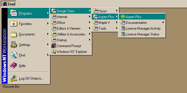
You must execute Aspen from one of the Chemical Engineering Department's PC in AL C126. To do so login to get a screen that is all blank except the top left corner which looks like:

Click with the left button on Start and follow the menus holding the button down until you see:

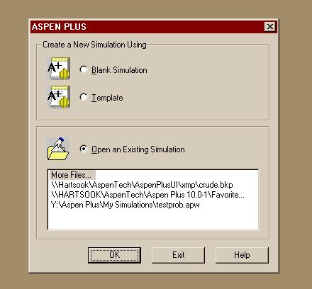
When you release the button Aspen should start, display a brief message and finally give you the following:

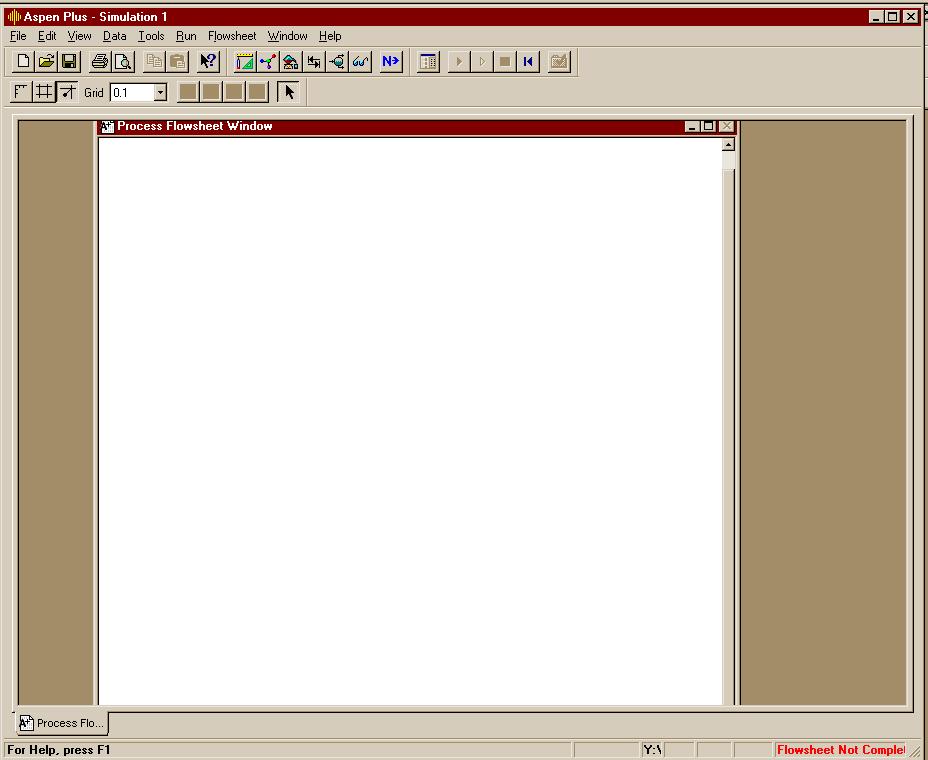
Change the selected button to Blank Simulation and click OK. Click OK to Connect to Engine on Local PC and then to acknowledge that the connection is established. You will then have an Aspen Simulation window enclosing a window with blank space to start your model of a part of a chemical plant. Note that the "blank" Process Flowsheet window should show the model icons at the bottom of the window. If it looks like:

then the icons are covered by the bar with the tab that says "Process Flo..". You need to expand the size of the "Process Flowsheet" window to leave enough room for the icons. If you click on the middle window control button
, you will find the icons at the bottom of the window.

Saving Your Work in Aspen
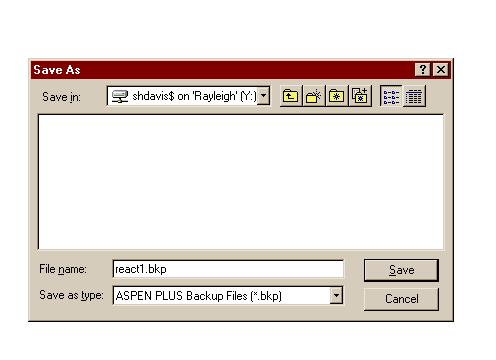
To save a work session, select "Save As" from the "File" menu on Aspen's main window. You should save your files in backup mode as opposed to the default mode that is shown when you first click on "Save As". Then give your file a name so the window looks something like:

Click the "save" button and you will be able to continue after loading that file in another session. You will also have some protection in case your simulation session runs into difficulties. You may save your files on the "Y" drive of the machine you use for such purposes or to your "Zip" disk.
 

P O U R I A

مدیر مهندسی شیمی مدیر تالار گفتگوی آزاد
مدیر تالار
Using Aspen

Using Aspen

Using Aspen

Building a model in Aspen consists of the following steps:


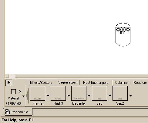
When creating the flow diagram, you may employ a variety of equipment. We have compiled a list of equipment icons which are commonly used in CENG 403 projects. These icons may be brought up and put on the flowsheet from the bottom of the main Aspen window. This is the way the bottom part of the screen looks when you first create a new blank window:
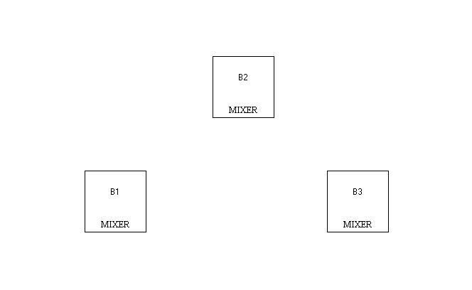
Note that there are nine different categories of units shown as "Tabs". The first category: Mixers/Splitters comes up as being selected when the window first opens, but you can select any of the others with the left button. Each of the categories then has several types of units shown as icons below the name of the category. The three types in the first category are the mixer and two types of splitters. The default icon for these is simply a box with the name shown below it. If you click on one of the icons, it will become lighter in color and you can then make a copy of it in the blank window by clicking at any position in the window. You can continue to add that same unit by additional clicks in the flowsheet space. For example clicking three times in the flowsheet after selecting the Mixer icon might produce:


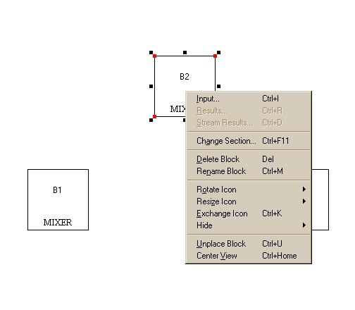
If you click on one of the icons it will be selected ( the corners will have colored squares on them and black squares will citcle the icon) and you can then do several things to it. Click the right button to bring up a menu that lists the operations and select among the one you want:

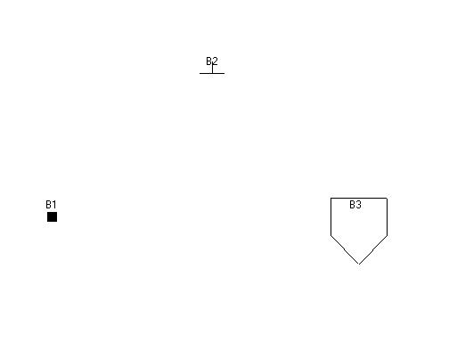
The most frequently used of the operations are: Delete, Rename, Rotate and Exchange Icon. If you select Exchange Icon, you will find there are lots of other ways to represent a mixer such as:


  • [*=left]Mix/Split
    Mixer - Mixes streams together.
    FSplit - Divides feed based on splits specified for the outlet streams.
    SSplit - Divides feed based on splits specified for each substream that may be entering the splitter. For example, an entering stream may be a mixed solid and liquid in the form of a slurry. The solids in the inlet may wind up preferentially in of of the exit streams from the unit.

    If you want to see a brief message describing the unit respresnted by one of the icons, place your cursor on the icon and you will find the message like the following one for FSplit:
If you want more information about the unit, place your cursor over the icon and (without clicking on it) hit the "F1" key. This should bring up a help window that will tell you more.


  • [*=left]Separators - There are five different spearators:

  • Flash2 - Two-outlet piece of equipment that allows you to model flash separations based on vapor-liquid equilibrium.
    Flash3 - Three outlet flash for systems that might produce a vapor and two liquid streams
    Decanter - Separator with two liquid outlet streams
    Sep & Sep2 - General separators of compounents in a stream
    [*=left]Heat Exchangers - Here are the five types of heat exchangers:

  • Heater - Extremely simple model of a heat exchanger. Basically allows you to determine the energy requirements of changing a stream's temperature.
    HeatX - Models a two-stream co-current or counter-current heat exchanger.
    [*=left]Columns - There are lots of columns:

  • DSTWU - One of two primary models of a distillation column. Of the two, DSTWU is the simpler, allowing you to model a column based on shortcut methods when you do not know many of the parameters.
    RADFRAC - Aspen's other model for a distillation column. Rigorous and complex, this model should only be used when you are extensively familiar with the system you are attempting to model.
    [*=left]Reactors - There are also lots of reactors:

  • RStoic - Models a reactor for given stoichiometry and extents of all reactions
    REquil - Models a reactor with some specified set of reactions assumed to be at thermodynamic equilibrium
    RGibbs - Models a reactor with minimum Gibbs Free energy
    RCSTR - Models a Continuous flow Stirred Tank Reactor (CSTR).
    RPlug - Used to model plug flow reactors.
    RBatch - Model of a batch reactor.
    [*=left]Pressure Changers - There are several ways to change the pressure in our system

  • Pump - Used when you need to simulate a pump in a flowsheet for transporting liquids.

    Compr - Polytropic or isentropic compressor for gases.


P O U R I A

مدیر مهندسی شیمی مدیر تالار گفتگوی آزاد
مدیر تالار
Creating a Model

Creating a Model

Creating a Model

Now that you have seen the majority of the pieces of equipment you will use during CENG 403, it is time to create a model using Aspen. The example presented here is the same as the one discussed in the section on flash separations in Aspen, except that the version here is more detailed so that you will become more familiar with Aspen.
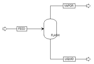
Below is a diagram of a flash separation unit in Aspen. We will demonstrate the steps needed to create such a diagram in an Aspen session.
This flow diagram was created in the following manner:


  • [*=left]Select "New" from the "File" menu in the main Aspen window. From the "New" menu, choose "General with Metric Units."
    [*=left]Click on the "Separators" Tab below the flow sheet space.
    [*=left]Click on the "Flash2" icon, place one copy in the flow sheet area (remember to turn off the insert mode with a click of the right button) and change the icon once or twice to get one that looks more like a flash tank.
At this point the left/bottom part of the window should look something like:


  • [*=left]It is recommended that you use the Aspen "Help" menu to find out about placing streams in the flow sheet. There is a topic called Placing Streams and Connecting Blocks that is pertinent to our job. You will need a feed stream and two product streams. If you click on the "STREAMS" icon to the left of the Separators icons, you can start placing all three streams on the diagram. When you are finished, you can turn off the stream placing mode by clicking on the arrow in the upper left part of the "STREAM" icon.
    [*=left]As each stream is finished, it will be named as a number by Aspen. You may change the name of the stream by clicking on the stream name with the left mouse button and then the right mouse button. From the menu that appears, choose Rename Stream with the right mouse button. You can also rename the unit the same way.
The flow diagram might look like this:
At this point, the first step in creating a model in Aspen, drawing a flow diagram, is complete. Click on the word "Next" icon:
in the upper-right-hand part of the Aspen window. A window should appear announcing that the "Flowsheet connectivity is complete." Click on the "OK" button.

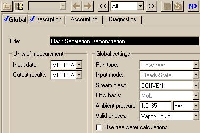
The next window to appear is the Setup Specifications window. For this example, no action is required, but we can add a "Title" and change units to be used globally. This is the way the window looked for our demonstration.
Note that the "setup" Folder is checked so we can go on to the next window by clicking the "Next" icon.
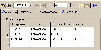
This next window is where you tell Aspen which components will be in the system. Fill in the window such that it looks like this:
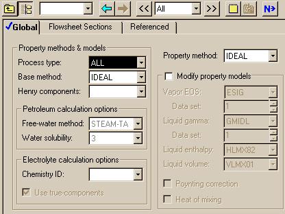
Once your component window looks like this one, click on the "Next" button again. The next window to appear allows you to specify which thermodynamics package you want to use to model the system. For this system, choose the ideal package. To do this, select "IDEAL" in the "Property methods & models" section as the "Base Method".

Once again, where you are finished with the window as shown by the check for "Properties" so you can hit the "Next" button. When you do so, you will encounter a message saying the required properties input is complete and you have to verify that you want to go on to the next "required" step.
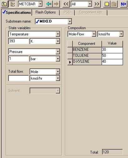
Now we need to specify the conditions of the feed stream. For this example, we will use 393 K and 1 bar.
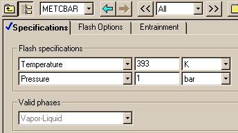
After you fill in your Stream FEED Input window, click on the "Next" button. The next window to appear is the last window for this system. In this window, you need to specify the conditions of the flash. For this example, we will use 393 K and 1 bar: the same numbers used in the first run in the section that deals with flash tanks in Aspen. This window should look like this:
Once you have done this, you have finished creating the model. To run the model, click on "Next," which causes Aspen to inform you that the required input is complete. Now choose "OK."
 

P O U R I A

مدیر مهندسی شیمی مدیر تالار گفتگوی آزاد
مدیر تالار
Executing a Model and Displaying Results

Executing a Model and Displaying Results

Executing a Model and Displaying Results

After you have entered all required data for your simulation, the "Next" button will bring up the message:
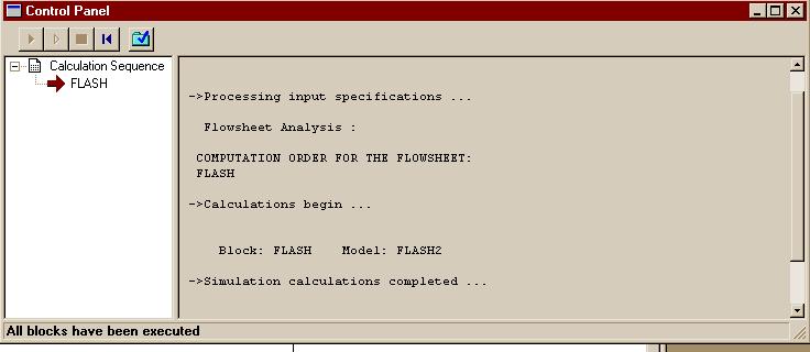
Clicking the "OK" button will then start execution of the simulation and show the Control Panel:
When executing a flowsheet in Aspen, it is wise to view the Control Panel as the run is proceeding. You may execute the simulation with "Run" in the Run menu, but the Control Panel allows you to witness the progress of the run. You may also cancel a run in mid-calculation via the control panel if you wish. Finally, it is also possible to pull up a results window using the Control Panel after calculations are complete.
You may scroll through the Control Panel window to learn more about the status of a run. For example, if the run had crashed, the control panel would have given us a reason for the failure. Keep in mind, though, that the Control Panel does not always give detailed information.
This image of the Control Panel indicates that the run was successfully completed. To access the results, click on the "Results" button:
in the Control Panel. If you are not running a Control Panel (you can always bring one up by using the "View" menu), you may access the results by choosing the procedure shown in the section on
annotating your diagram.

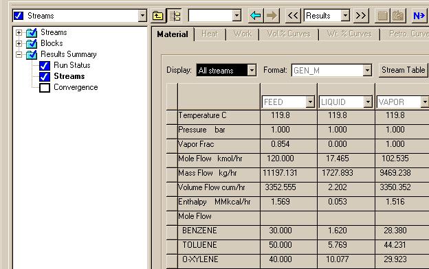
When the results page appears, the first information it displays is little more than a cover page. To get to more important data, select "Results Summary - Streams" to see:
This selection in the Results window summarizes the system's stream data.
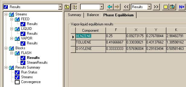
If you click on ">>" button next to the window that says "Results", you will move to other sections of the Results. For instance, clicking on ">>" several additional times yields the following window:
This window is important in that it provides the same information that is found by modeling a flash tank with the Matlab software.
 

P O U R I A

مدیر مهندسی شیمی مدیر تالار گفتگوی آزاد
مدیر تالار
Adding Tables and Text to Flow Diagrams

Adding Tables and Text to Flow Diagrams

Adding Tables and Text to Flow Diagrams

The basic flow diagram that was used to demonstrate creating and executing a model looked like.
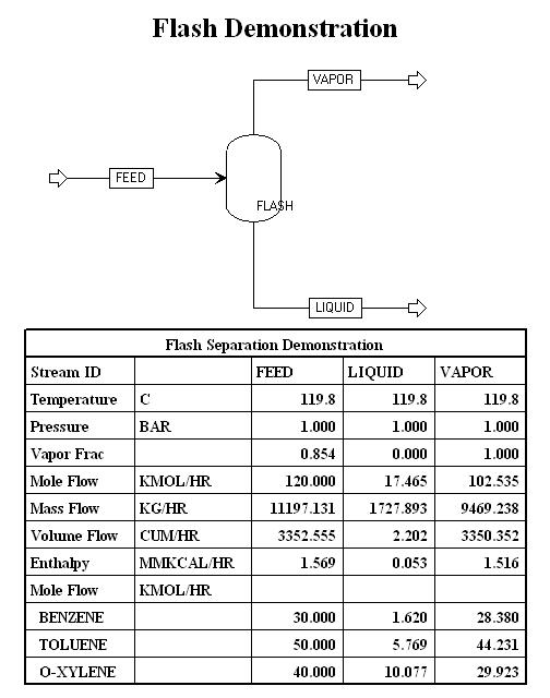
We may add a title (and other text) and a Table of stream data to make the diagram more useful in reports. Here is an example:
Aspen Help may be very useful in finding out how to annotate you flow diagrams. It may be done in standard or PFD mode. In older versions of Aspen the use of the PFD mode was essential, but it appears to be less useful in Aspen 10.


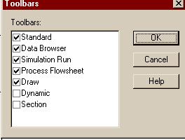
  • [*=left]First: to add text to your diagram, you need to display the toolbar for drawing. This can be done by:
    • bring up the View menu,
    • select the Toolbar option,
    • turn on the "Draw" bar.

This will cause the Draw bar to be displayed as a third line of toolbars:
This gives you the standard tools for drawing: for example the A button allows you to enter text that may be made bold, italicized or uderscored with the last three buttons. You can also change the font and size of font with the two selectors preceding those three. You can also draw figures and lines as on most other drawing programs.


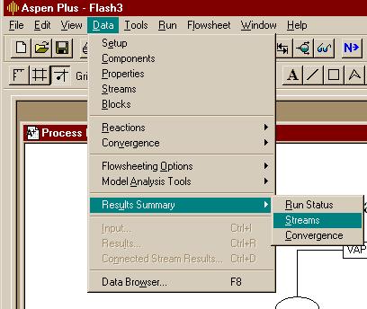
  • [*=left]Next: to add a Flow table, you need to display the table of stream results by:

Then you should find the Stream Results Table displayed:
Click the "Stream Table" button to have that table inserted in your diagram.
 

P O U R I A

مدیر مهندسی شیمی مدیر تالار گفتگوی آزاد
مدیر تالار
Sensitivity Runs in Aspen

Sensitivity Runs in Aspen

Sensitivity Runs in Aspen

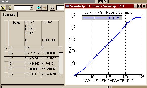
A sensitivity run in Aspen allows you to vary one element of a system, such as the temperature of a reactor, and then view the effects this variance has on other aspects of the system, such as the mole composition of the reactor effluent. As part of the example of creating a flash tank model in Aspen, we will use a sensitivity run to show how the fraction vapor changes with the flash temperature for fixed feed and pressure.
Since we already have a flash file created, we will use it to create the sensitivity run. There are many steps to follow, but some that are shown here may not be required. If you find a better or simpler way to do this, let us know so we can correct our notes. Here are the steps we followed:


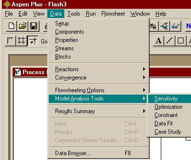
  • [*=left]First create a sensitivity tool window by:


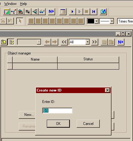
  • [*=left]Second, give the sensitivity run a name or accept the default by clicking "OK" in the window. In most cases, we will simply click on the "Next" button to go on to further steps.


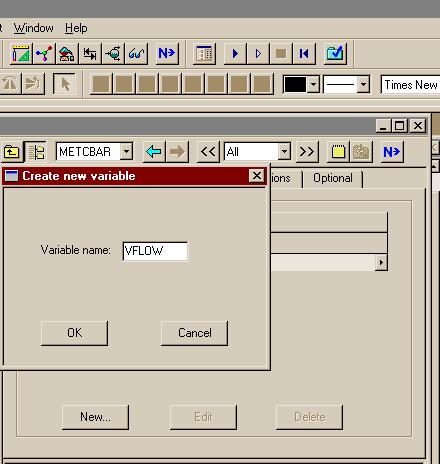
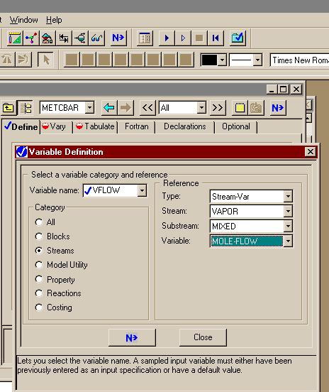
  • [*=left] Third, create a defined variable to be sampled. We created the variable VFLOW by pressing the "New" button:


  • [*=left] VFLOW is in the "Streams" category, of type "Stream-Var", in the stream "VAPOR", and it holds the "MOLE-FLOW". The substream is mixed, but that is the default value.


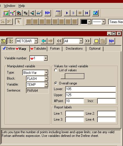
  • [*=left] Using the "Next" button allows us to bring up a window in which we can set the Variable Numer as "1" by clicking on "New" and then specify that:
    • it is the "TEMP
    • of type "Block-Var"
    • in the block "FLASH".
    • We specify the range as 105C to 125C with 10 points used in that range.
    Note that the window does not show the units for temperature, you must deduce this from the fact that we are using the "METCBAR" units.


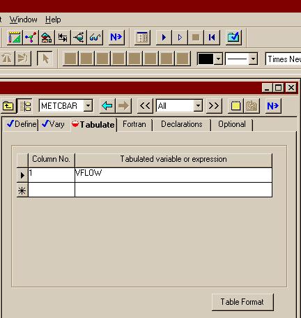
  • [*=left] We will tabulate "VFLOW" in the first column of out results.


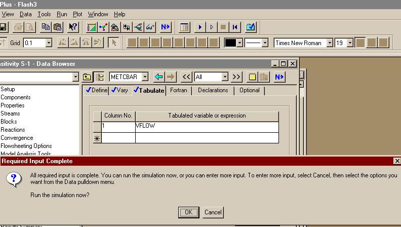
  • [*=left] We see (using the "Next" button again) that we have finished setting conditions for the sensitivity run and can click "OK" to execute the program.


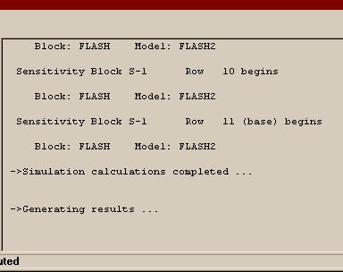
  • [*=left] Note that in the "Control Panel" you can see that 11 flash operations were performed.


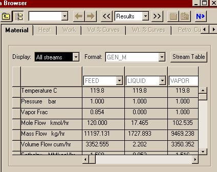
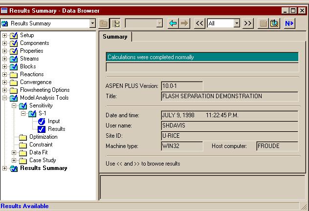
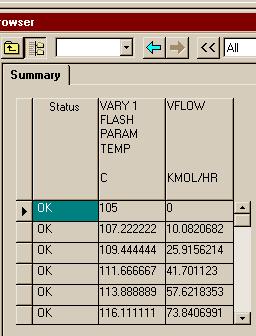
  • [*=left] Here is the first result window that is displayed. If you click on the "<<" button you will find the sensitivity results.


  • [*=left]They list the vapor flow rate for each flash temperature. Now let's plot those results:


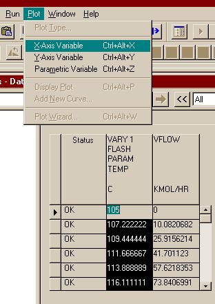
  • [*=left] If you a) click on the head of the "TEMP" column and then b) use the Plot menu, you can make a plot with those temperatures as the X-Axis Variable.


  • [*=left]If you a) click on the head of the "VFLOW" column and then b) use the Plot menu, you can make a plot with the flows as the Y-Axis Variable. Then you can use the "PLOT" menu to display the plot as seen below.
 

A.R-KH-A

عضو جدید
کاربر ممتاز
سلام
من یه سوال تو نرم افزار اسپن داشتم..

برای یه میکسر وقتی دو ورودی داشته باشیم و یک خروجی، و فقط دبی یک جریان ورودی معلوم باشه؛ میشه دبی جریان های دیگه رو بدست آورد؟

شرایط مسئله :
input:
___
Flow1=100kmol/h
Compotion=
100%= A
B =0%
___
Flow 2 = ?
Comption=
A=20%
B=80%
___________________________
output
Flow3=?
Comption
A=95%
B=5%
____________________________
بجای A و B هر ماده ای میخاین بزارین..

توی هایسیس واس حلش مشکلی نداره و جریانهای دبی رو با کمی تنظیم بهتون میده ولی تو اسپن بدین صورت نیست و چون جریان 2 ،دبی نداره و اجزاء براش مشخص شده ران نمیشه!

راه حلش توی اسپن بدون استفاده از ابزارهای دیگه بدون دیزاین اسپک و.. چیه؟؟
ممنون میشم جواب بدین
 
آخرین ویرایش:

ئدز

عضو جدید
فکر کنم باید یه رنج براش تعریف کنید و گام و بعد ران کنید من با هایسیس کار نکردم شاید خودش با توجه به اطلاعات ورودی یه تخمینی بزنه اما تو اسپن برای مواردی مثل پیدا کردن یه حالت بهینه باید رنج تعیین کنید فعلا جزوم در دسترس نیست و گرنه کامل میگفتم چه جوری
 

A.R-KH-A

عضو جدید
کاربر ممتاز
فکر کنم باید یه رنج براش تعریف کنید و گام و بعد ران کنید من با هایسیس کار نکردم شاید خودش با توجه به اطلاعات ورودی یه تخمینی بزنه اما تو اسپن برای مواردی مثل پیدا کردن یه حالت بهینه باید رنج تعیین کنید فعلا جزوم در دسترس نیست و گرنه کامل میگفتم چه جوری
اره تا الان که اینطور نشون میده باید با رنج کار کرد تا جوابو بده.. در حالی که هایسیس اول ارور میده ولی با کمی تنظیم بدون استفاده از حالت بهینه اش جواب رو میده..
واسم جالبه که اسپن واس یک کار کوچیک باید رنج براش تعیین کنی... البته شاید دوستان روشی بلد باشند که نیاز به این کارا نباشه
 

ئدز

عضو جدید
کتابی هست که اسپن یا هاسیس رو خیلی خوب و با مثال های به درد بخور یاد داده باشه ماشااله کلاسا زیر میلیون نیست.................
 

A.R-KH-A

عضو جدید
کاربر ممتاز
کتابی هست که اسپن یا هاسیس رو خیلی خوب و با مثال های به درد بخور یاد داده باشه ماشااله کلاسا زیر میلیون نیست.................

جزواتی که بچه ها تو تالار گذاشتن خیلی خوبن.. ازشون استفاده کنی خوبه..
 

eghbali66

کاربر حرفه ای
کاربر ممتاز
اره تا الان که اینطور نشون میده باید با رنج کار کرد تا جوابو بده.. در حالی که هایسیس اول ارور میده ولی با کمی تنظیم بدون استفاده از حالت بهینه اش جواب رو میده..
واسم جالبه که اسپن واس یک کار کوچیک باید رنج براش تعیین کنی... البته شاید دوستان روشی بلد باشند که نیاز به این کارا نباشه
بله دوست من، برای حالت پیش فرض اسپن که SM (Sequetail modular) هست، همینجوریه. یعنی باید اطلاعات جریانهای ورودی و بلوک مشخص باشه، تا اطلاعات جریانهای خروجی رو بهت بده، البته این روش محاسبات رو میشه تغییر داد. ضمن اینکه در حالت SM برای بعضی بلوکها مثه مبدل حرارتی یه سری بلوکهایی تعریف شده که محاسباتی مانند حالتی که گفتین رو انجام میده...
این یه نقص نیست، چون وقتی میری تو شبیه سازی فرآیندهای بزرگ، فقط نزدیک بودن اطلاعات جریانهای خروجی با داده های واقعی ملاک شبیه سازی قوی هست
 

A.R-KH-A

عضو جدید
کاربر ممتاز
بله دوست من، برای حالت پیش فرض اسپن که SM (Sequetail modular) هست، همینجوریه. یعنی باید اطلاعات جریانهای ورودی و بلوک مشخص باشه، تا اطلاعات جریانهای خروجی رو بهت بده، البته این روش محاسبات رو میشه تغییر داد. ضمن اینکه در حالت SM برای بعضی بلوکها مثه مبدل حرارتی یه سری بلوکهایی تعریف شده که محاسباتی مانند حالتی که گفتین رو انجام میده...
این یه نقص نیست، چون وقتی میری تو شبیه سازی فرآیندهای بزرگ، فقط نزدیک بودن اطلاعات جریانهای خروجی با داده های واقعی ملاک شبیه سازی قوی هست

اره میخاستم بگم شاید روش محاسباتی رو باید تغییر داد که تو جزوه مهندس رازی فر دیدم به این اشاره کرده..
حرفاتون درسته مهندس..
 

eghbali66

کاربر حرفه ای
کاربر ممتاز
سلام، کسی در مورد شیرین کردن آب دریا (حذف نمک از آب) فرآیند شبیه سازی شده دیده؟
 
بالا